Before you begin
 Use approved ESD procedures to prevent damage.
Attention:
- This is not a stand-alone procedure. Customer disruption and damage to the hardware might occur if microcode and power boundaries are not in the proper conditions for this service action.
- If you were sent here by a serviceable event FRU repair, the microcode and power boundaries have already been set.
- If you were not sent here by a serviceable event FRU repair, see MAP1230 Replace a FRU without using a serviceable event.
Notes:
- All the cables and FRUs to be removed must be uniquely identified so they can be reinstalled correctly.
- If an installed earthquake resistance kit prevents you from accessing this FRU, refer to MAP1600.
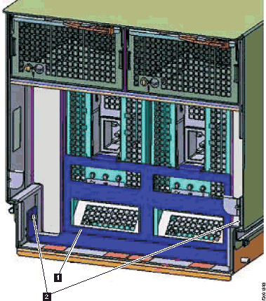
 to the alternate service position
  . Refer to
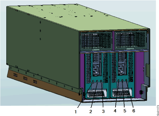
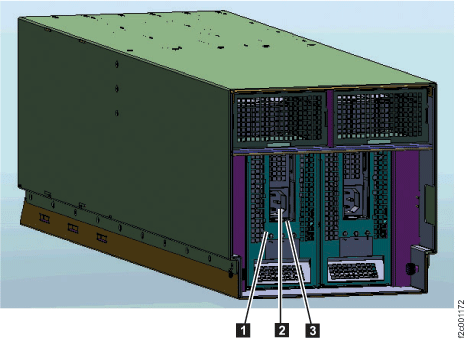
 on the I/O enclosure power supply must be
lit before going to the next step. This will ensure that the I/O enclosure
remains powered on when the failing power supply is removed. If the
power good LED is not lit, DO NOT CONTINUE. Instead
on the I/O enclosure power supply must be
lit before going to the next step. This will ensure that the I/O enclosure
remains powered on when the failing power supply is removed. If the
power good LED is not lit, DO NOT CONTINUE. Instead  input power to power supply
 and
and  identify for I/O enclosure power supply