Before you begin
 Use approved ESD procedures to prevent damage.
Procedure
- Non-service position. See Figure 1.
- Close the laptop display.
- Push the management console tray into the rack.
- Fasten the left and right thumbscrews.
Figure 1. Management console in non-service position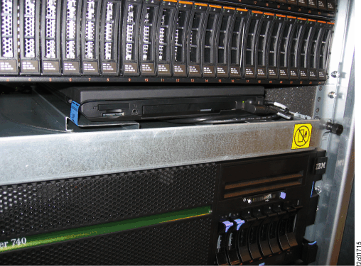
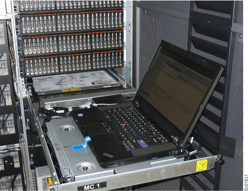
- Standard service position. See Figure 2.
- Open the laptop display. Note: The Model 961 laptop does not rotate to face the front.Figure 2. Management console standard service position
- Open the laptop display.
- Alternate service position. See Figure 3.
- At the left and right sides of the upper DC-UPS, unlatch
each slide rail
 and slide it fully out until it locks
into position. See Figure 4.
and slide it fully out until it locks
into position. See Figure 4. - Release the laptop and sheet metal assembly from the
management console tray. See Figure 5.
- Lift up each release latch and twist it 1/4 turn so it stays
in the up position
- Slide the assembly in toward the rack, from the latched
 position to the unlatched
  position.
- Lift up each release latch
- Move the laptop to the left and set it down on the DC-UPS
slide rails. See Figure 3.
- Pull it away from the rack to engage the slots
 that fasten it to the slide rails.
 - Twist each release latch until it drops down to prevent the
laptop from moving on the slide rails.
- Pull it away from the rack to engage the slots
- Ensure the laptop cable bundle excess is on the laptop
tray
 . See Figure 3.
Figure 3. Alternate service position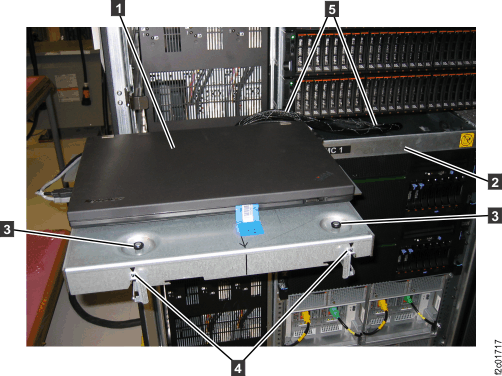 Figure 4. Battery service module (BSM) set enclosure slide rails
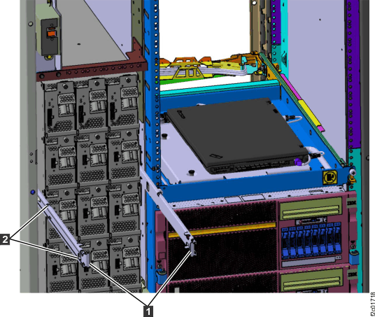 Figure 5. Management console standard service position
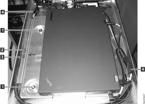
- At the left and right sides of the upper DC-UPS, unlatch
each slide rail