DS8000 Service Documentation Version 7.5
Checking cables on all racks
Procedure
- At the rear of Rack-1, do the following steps
at the rear of both CEC enclosures:
- Ensure that the following private network Ethernet cables are connected:
- A black Ethernet cable is connected to P1-T5 (top) and P1-C2-T1
(top)
- A gray Ethernet cable is connected to P1-T6 (bottom) and P1-C2-T2
(bottom)
Figure 1. CEC enclosure PCIe and
Ethernet locations (rear)
- Gently push on each PCIe cable to ensure that it is
latched. See Figure 1.
- P1-C1-T1/T2/T3
- P1-C3-T1
- P1-C4-T1
- P1-C8-T1/T2/T3 (if present)
- At the rear of Rack-1 check the following cables,
See Figure 2 and Figure 3.
- Ensure that only black Ethernet cables are connected
to the SW1 (left) Ethernet switch.
- Ensure that only gray Ethernet cables are connected
to the SW2 (right) Ethernet switch.
- If you find any misplugged cables, use the cable location
labels to properly connect them.
Note: A cross-connected cable may cause the installation
to fail and require next level of support to recover.
Figure 2. Ethernet switch tray locations
(Model 961, rack version 1)
Figure 3. Ethernet switch tray locations
(Model 961 rack version 2 rear)
- At the front of the rack, with the management console laptop
tray pulled out to the service position, check the cable connections
as shown in Figure 4:
- Ensure that the black Ethernet cable and black USB cable
connect to the same USB Ethernet adapter.
- Ensure that the gray Ethernet cable and gray USB cable
connect to the same USB Ethernet adapter.
Figure 4. ThinkPad laptop USB Ethernet
adapter cables (rack version 1 shown, rack version 2 similar)
- For T520 and T530 management
consoles, ensure the power, Ethernet, USB modem, and USB Ethernet
cables are securely connected. See Figure 5.
- Black cable from USB Ethernet adapter to left side,
upper USB for eth0 (black)

- Gray cable from USB Ethernet adapter to left side, lower
USB for eth3 (gray)

- USB modem cable to rear USB for modem

- Ethernet cable from front of rack to Ethernet connector
for eth2 (customer)

- Power cable to the power connector

Figure 5. ThinkPad T520, T530 laptop
unit cable connections
- For T540 management consoles,
ensure the power, Ethernet, USB modem, and USB Ethernet cables are
securely connected. See Figure 6 and Figure 7.
- Black cable from USB Ethernet adapter to left side,
front USB for eth0 (black)
 (Figure 6)
- Gray cable from USB Ethernet adapter to left side, rear
USB for eth3 (gray)
 (Figure 6)
- USB modem cable to right side, rear USB for modem (Figure 7)
- Ethernet cable from front of rack to Ethernet connector
for eth2 (customer) (Figure 6)
- Power cable to the power connector (Figure 6)
- Power cable to the power on card connector near (Figure 6)
Figure 6. ThinkPad T540 laptop unit
cable connections (left and rear)
Figure 7. ThinkPad T540 laptop unit
cable connections (right)
- At the rear of each I/O enclosure for Rack-1
and Rack-2 (if present), gently push on each PCIe cable (P1-C7-T1
and P1-C7-T2) to ensure that it is latched, see Figure 8.
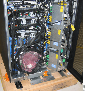
- If Rack-1 has a coil of PCIe and SPCN cables behind
the I/O enclosures as shown in Figure 9, loosen the
cable tie at the top of the coil and move it temporarily out of the
way.
Figure 8. I/O enclosure PCIe cable
locations (rear)
Figure 9. Rack-1 PCIe and SPCN cable
coil for shipping
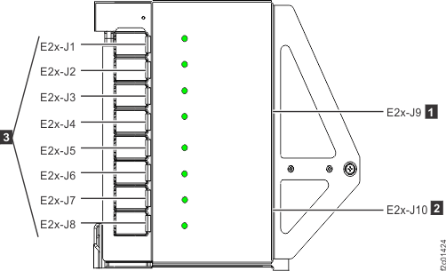
- At the rear of each rack behind the DC-UPS power
supplies, ensure all power cables connected to each power distribution
unit (PDU) connector J1-J10 are fully seated. See Figure 10.
Figure 10. Locations for power distribution
unit (PDU) connectors
- Will the Rack-1 you are installing be connected
to an existing Rack-1 (already installed) by private network cables
(gray and black)?
- Yes. The two Rack-1s will share their internal management
consoles (primary and secondary roles). The management console in
new Rack-1 must be temporarily disconnected from the private network.
Go to Checking management consoles (HMCs) if installing second Rack-1.
- No. The new Rack-1 will not be connected to an existing Rack-1.
Go to the next step.
- Does the new storage facility to be installed
have one or more storage expansion racks?
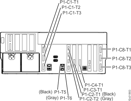
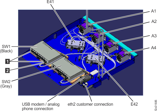 Figure 3. Ethernet switch tray locations (Model 961 rack version 2 rear)
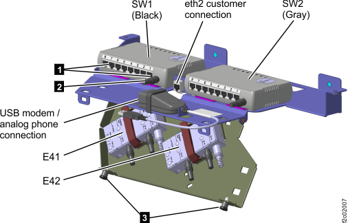
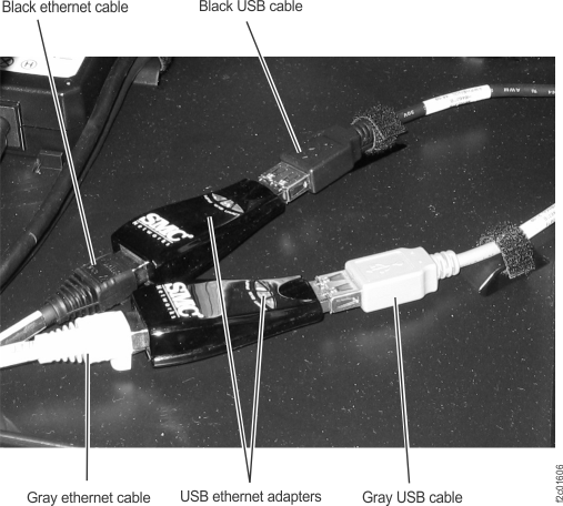
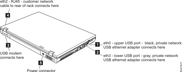
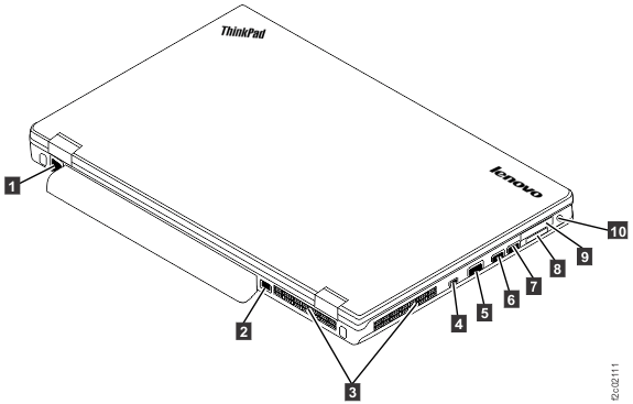 Figure 7. ThinkPad T540 laptop unit cable connections (right)
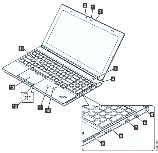
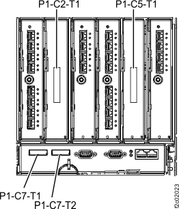 Figure 9. Rack-1 PCIe and SPCN cable coil for shipping