MAP4085 Section-2
Procedure
- Launch the Advanced System Management Interface (ASMI)
for the CEC enclosure being repaired. The CEC enclosure being repaired
is in Power Off status.
- From the navigation area, click Storage Facility Management > storage facility > Server View > server.
- From the bottom Task area, click Operations > Launch Advanced System Management (ASM).
- On the Launch Advanced System Management (ASM) confirmation window, click OK.
- If the This Connection is Untrusted window opens, click Add Exceptions. When the Add Security Exception window opens, click Confirm Security Exception.
- The management
console Web browser
will be launched, and the ASM login panel will display. Note: If access fails and you have a laptop available, try MAP6F20 Accessing the ASMI using a web browser.
- In the ASMI login panel, check the User Status table in the right pane. Does the table show user ID dev as Enabled?
- Log in as user ID admin with password admin2107.
- Use the ASMI to enable
user ID dev.
- In the navigation area, expand Login Profile and select User Access Policy.
- In the User ID dropdown menu, select dev.
- In the Policy setting dropdown menu, select Enabled.
- Click Continue.
- Log out of ASMI, but do not close the ASMI login panel.
- Continue with step 5.
- Log in as user ID celogin and
the password FipSce. Notes:
- If you are logged in and not active for 15 minutes, your session expires
- If you make five invalid attempts, your user account is locked out for five minutes and none of the other accounts are affected.
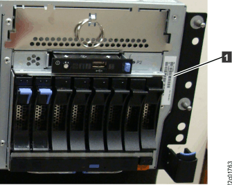
- Determine and record the CEC enclosure feature,
sequence, and serial number.
- Refer to the vertical label to the right of the
CEC control panel. The front cover must be removed to view the label.
See Figure 1. Note: Do not refer to the MTMS (Machine Type Model Serial number) label on the left side of the front cover.Figure 1. CEC enclosure feature code label
- Refer to the vertical label to the right of the
CEC control panel. The front cover must be removed to view the label.
See Figure 1.
- Use the ASMI to set the CEC enclosure feature,
sequence, and serial number. Note: The feature code and sequence number for 8205-E6C or 8205-E6D system backplane is 78AA-001. The feature, sequence, and serial number must be entered for all system backplane replacements.
- In the navigation area, expand System Configuration and then scroll down to select Program Vital Product Data.
- Select System Enclosures. In the right pane, the current
system enclosure (CEC enclosure) is displayed. Note: The system planar VPD has not been set yet, so the enclosure location is displayed as: U.
- Click Continue.
- Enter the feature code number 78AA-001 in the Feature Code/Sequence Number field.
- Enter the enclosure serial number recorded from the previous step.
- Leave the reserved field blank. See Figure 2.
- Click Save settings.
- The System enclosure operation completed successfully screen is displayed. The service processor reboots.
Figure 2. ASMI System Enclosures VPD window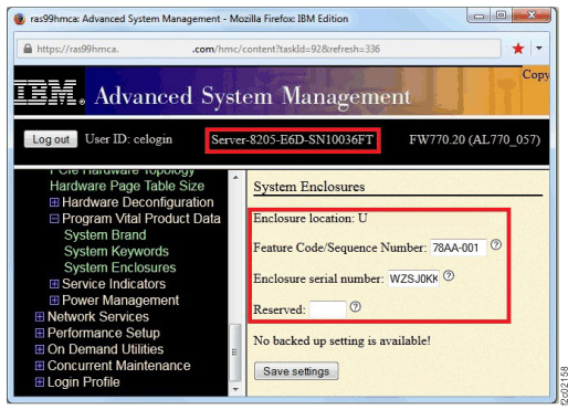
- Display the date and time settings of the partner CEC enclosure
that is not being repaired.
- Display the ASMI login window for the CEC enclosure that is not being repaired.
- The date and time are displayed on the login window.
- Use the F5 key to refresh the date and time.
- Set the Time of Day for the CEC enclosure being repaired
to be within 2 minutes of the partner CEC Time of Day. Note: You should still be logged in to the ASMI menus of the CEC being repaired unless it has been more than 15 minutes, in which case you have been logged out.
- From the ASMI navigation, expand System Configuration and then select Time of Day under System Configuration.
- Use the F5 key to refresh the date and time settings on the partner CEC ASMI login window.
- Reference the date and time setting on the partner CEC enclosure and then enter it on the CEC enclosure being repaired. It must be entered in Universal Coordinated Time (UTC) and must be within 2 minutes of the partner CEC Time of Day.
- Click Save settings. A confirmation displays. Continue at the next step.
- Determine if the Logical Memory Block Size
(LMB Size) is displayed by using the ASMI menu for the CEC enclosure
being repaired.
- From the ASMI navigation, select Performance Setup, then select Logical Memory Block Size.
- If the Automatic field is displayed, ignore it's value.
- Is the LMB Size displayed in the Setting field?
- Yes, go to step 16.
- No, if this is your first time through this step go to the next step. If this is your second time through the No answer, stop and call the next level of support.
- Determine if the server state is Power Off.
- From the navigation area, click Storage Facility Management > storage facility > Server View.
- From the right work area, observe the Status column.
Is the status Power Off?
- Yes, go to step 14
- No, go to the next step.
- Change the server state to Power Off:
- From the navigation area, click Storage Facility Management > storage facility > Server View.
- From the right work area, select the CEC enclosure being repaired.
- From the bottom Task area, click Service Utilities > Storage System Power Control.
- The System Power Control window opens. Click Power Off System.
- A confirmation window opens. Click Yes.
- A success window opens. Note: This means the power off command was executed. The CEC enclosure is starting its power off sequence.
- Wait up to 5 minutes for a confirmation that the power off operation was successful.
- Was the Power Off operation successful?
- Yes, do not close the System Power Control window. Continue at the next step.
- No, try the power off operation again until it is successful, or call the next level of support.
- Observe the status of the server. Wait for the server to be in the Power Off state, and then go to the next step.
- Change the server state to Standby:
- From the navigation area, click Storage Facility Management > storage facility > Server View.
- From the right work area, select the appropriate CEC enclosure.
- From the bottom Task area, click Service Utilities > Storage System Power Control.
- The System Power Control window opens. Click Power On System to Standby.
- A confirmation window opens. Click Yes.
- A success window opens. Note: This means the power on to standby operation was executed. The CEC enclosure is starting its power on to standby sequence.
- The CEC enclosure fans go into high speed mode and the CEC enclosure status changes to Initializing.
- Wait up to 10 minutes for the CEC enclosure to change
to Standby status.
Is the CEC enclosure displaying in Standby status?
- Change the server state back to Power Off (use the procedure in step 12) and then return to step 10 to display the LMB setting.
- Is the displayed LMB Size Setting equal
to 16? Note: The value displayed in the Automatic field can be ignored. The Setting field must be 16.
- Yes, continue at the next step.
- No, change the setting to 16. Then continue at the next step.
- Click Save Settings even if you
did not change the LMB settings. A confirmation window opens.
- The Service Processor might reboot at this point. Wait until the Service Processor returns to the Power Off state before you continue with the next step.
- Log out and close any ASMI windows that are open.
- Close any System Power Control windows that are open.
- Close this window, then return to the HMC repair process window that sent you here and click Next to continue.