MAP2700 Section-2 One or more storage enclosure power supplies reporting power loss
Procedure
- Does the FRU list for the serviceable event that sent you
here, include a storage enclosure power supply?
- Yes. Not all storage enclosure power supplies attached to this PDU are reporting loss of input power, or only one storage enclosure power supply is attached and reporting loss of input power. Go to step 3.
- No. There are at least two storage enclosure power supply units attached to this PDU, and all are reporting loss of input power. Continue with the next step.
- Do the following in the order listed.
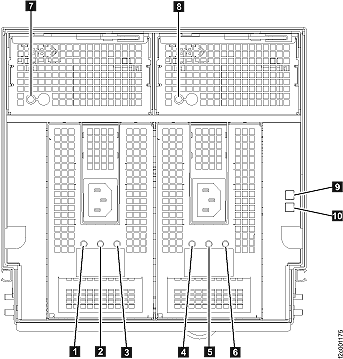
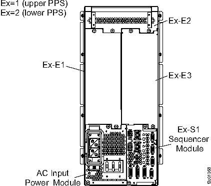
- Locate the PDU listed in the serviceable event FRU list.
- Ensure there are no loose or disconnected
cables for the PDU input and output connectors. If a problem is found,
you will reconnect or replace the cable(s), as applicable.
You will perform a pseudo-repair of the PDU. Instead of replacing the PDU, reconnect or replace the power cable(s). After the repair process is complete, you will exit this MAP. Go to MAP2700 Section-6 Exit this map and exchange or pseudo-repair a FRU to continue the repair process and perform a pseudo-repair of the PDU listed in the FRU list.
- Replace the PDU.
After the repair process is complete, you will exit this MAP. Go to MAP2700 Section-6 Exit this map and exchange or pseudo-repair a FRU to continue the repair process and replace the PDU listed in the FRU list.
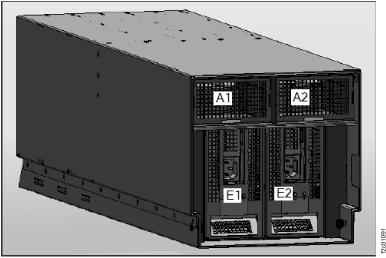
Figure 1. Power distribution units (PDUs) location codes
- Locate the storage enclosure power supply listed in the serviceable event FRU list.
- Observe the storage enclosure power supply
LEDs.
Find the condition that applies:- The Attention LED
 is lit, the DC Input Good LED
  is off. Input power is missing, go
to step 6.
is off. Input power is missing, go
to step 6. - Attention LED is lit, DC Input Good LED is lit and the DC Output Good LED
 is lit or off. Go to step 5.
 - All LEDs , , and are off. Go to step 5.
- The Attention LED is off, the DC Input Good LED is lit, and the DC Output Good LED is lit. The failure is no longer occurring,
exit this MAP and close the serviceable event that sent you here.
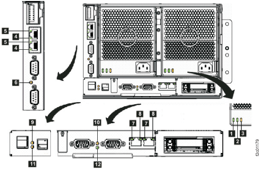
Figure 2. Storage enclosure power supply LEDs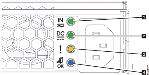
Table 2. Storage enclosure power supply LEDs Index LED name LED color Controlled by LED state Description 1 DC Input Good Green Hardware Solid on DC input good Off DC input not within limits 2 DC Output Good Green Hardware Solid on DC output good Off DC output is off 3 Identify / Attention Amber Microcode Solid on Fault Blinking This FRU being identified Off Default state 4 Not used Blue Microcode Off Default state, unused - The Attention LED
- The storage enclosure power
supply is failing, replace it.
After the repair process is complete, you will exit this MAP. Go to MAP2700 Section-6 Exit this map and exchange or pseudo-repair a FRU to continue the repair process and replace the storage enclosure power supply listed in the FRU list.
- The storage enclosure power
supply is either not receiving input power or has an internal failure.
Locate the power cable at the power supply and trace it to the PDU.
Is the cable properly connected at both ends and not visibly damaged?
- Yes, go to step 7.
- No, you will reconnect or replace the cable, as applicable.
You will perform a pseudo-repair of the power supply. Instead of replacing the power supply, reconnect or replace the power cable. After the repair process is complete, you will return here and go to MAP2700 Section-2 One or more storage enclosure power supplies reporting power loss, step 4 to confirm power supply operation. Go to MAP2700 Section-6 Exit this map and exchange or pseudo-repair a FRU to continue the repair process and perform a pseudo-repair of the power supply listed in the FRU list.
- At the PDU output connector that supplies this storage enclosure power supply, is the output power green LED lit?
- The possible failing
FRUs are the storage enclosure power supply and power cable.
Has the storage enclosure power supply already been replaced?
- Yes, you will now replace the storage enclosure power cable.
You will perform a pseudo-repair of the power supply. Instead of replacing the power supply, replace the power cable. After the repair process is complete, you will return here and go to MAP2700 Section-2 One or more storage enclosure power supplies reporting power loss, step 4 to confirm power supply operation. Go to MAP2700 Section-6 Exit this map and exchange or pseudo-repair a FRU to continue the repair process and perform a pseudo-repair of the power supply listed in the FRU list. - No, you will now replace the storage enclosure power supply.
After the repair process is complete, you will return here and go to MAP2700 Section-2 One or more storage enclosure power supplies reporting power loss, step 4 to confirm power supply operation. Go to MAP2700 Section-6 Exit this map and exchange or pseudo-repair a FRU to continue the repair process and replace the storage enclosure power supply listed in the FRU list.
- Yes, you will now replace the storage enclosure power cable.
- If a PDU port LED is off,
and other port LEDs on the same PDU are lit, the port fuse is blown.
The PDU will be replaced, but you will first attempt to isolate any additional failed parts. Do the following:- YOU MUST UNPLUG the storage enclosure power cable at the failing PDU output port before continuing.
- Disconnect the power cable from the storage enclosure power supply.
- Inspect both ends and the entire length of the power
cable looking for any evidence of a short.
Was visible evidence of a cable short found?
- Yes, replace the power cable at this time. Leave both ends of the power cable disconnected. No guided repair process is necessary. Next, you will prepare to isolate a power supply problem. Continue to step 10.
- No, visible evidence was not found. Leave both ends of the power cable disconnected. To further isolate a power supply or cable problem, continue to step 10.
- This step will isolate
whether the power cable has an internal short that caused the PDU
output fuse to blow.
- At the storage enclosure power supply, disconnect the power cable (if not already disconnected).
- At the failing PDU, ensure the power cable from the storage enclosure enclosure power supply is still unplugged.
- AT THE SAME FAILED PDU, find an available output connector with the port LED lit.
- Temporarily connect the power cable to the available PDU connector with the port LED lit.
After connecting the cable, is the port LED still lit?
- Yes, it is lit. The power cable does not have a solid short. Go to step 11.
- No, it is off. The power cable has a short and must be replaced along with the PDU. You will use a single repair action of the PDU with the failed port to replace both the cable and the PDU. During the repair, connect the power cable to the original PDU port. After the repair process is complete, you will return here and go to MAP2700 Section-2 One or more storage enclosure power supplies reporting power loss, step 4 to confirm power supply operation. Go to MAP2700 Section-6 Exit this map and exchange or pseudo-repair a FRU to continue the repair process and replace the PDU listed in the FRU list.
- This step will isolate
whether the storage enclosure power supply has an internal fault that
caused the PDU output fuse to blow.
- At the storage enclosure power supply, connect the power cable.
After connecting the cable, is the PDU port LED still lit?
- Yes, it is lit. The storage enclosure power supply and existing power cable do not have the fault condition present at this time. Go to step 12.
- No, it is off. The power supply is failing and has blown
the PDU fuse.
You will replace the storage enclosure power supply first, and then the PDU. Go to step 13.
Note: If you do not have a PDU FRU onsite and you want to temporarily restore the redundant power to the storage enclosure while waiting for the FRU to arrive, you can disconnect the cable from the failing PDU output connector and connect it to an output connector (if available) on the SAME PDU with the port LED lit. Ensure you label the cable at the connector to remind the person who replaces the PDU to properly plug the cable back to the original connector. DO NOT connect the power cable to a different PDU. Connecting to the wrong PDU can cause incorrect isolation of further power problems. - You will attempt to recreate
the intermittent fault condition to isolate the failing FRU. Gently
move and flex the power cable along its full length. If you recreate
the fault, the PDU port LED will change from lit to off.
Is the PDU port LED now off?
- Yes, it is off.
You have recreated an intermittent fault in the power cable. You will use a single repair action of the PDU with the failed port to replace both the cable and the PDU. During the repair, connect the power cable to the original PDU port. After the repair process is complete, you will return here and go to MAP2700 Section-2 One or more storage enclosure power supplies reporting power loss, step 4 to confirm power supply operation. Go to MAP2700 Section-6 Exit this map and exchange or pseudo-repair a FRU to continue the repair process and replace the PDU listed in the FRU list. - No, it is lit.
You have not recreated a cable fault, but the PDU still has a failed port and will be replaced. During the repair, connect the power cable to the original PDU port. After the repair process is complete, you will return here and go to MAP2700 Section-2 One or more storage enclosure power supplies reporting power loss, step 4 to confirm power supply operation. Go to MAP2700 Section-6 Exit this map and exchange or pseudo-repair a FRU to continue the repair process and replace the PDU listed in the FRU list.Note: You could also replace the power cable if you have that available.
- Yes, it is off.
- You will use MAP2700 Section-6 Exit this map and exchange or pseudo-repair a FRU to replace more than one FRU in the
FRU list: the affected power supply first, and then the PDU.
When the power supply replacement has been completed in MAP2700 Section-6 Exit this map and exchange or pseudo-repair a FRU step 3, continue with MAP2700 Section-6 Exit this map and exchange or pseudo-repair a FRU step 4 to replace the PDU. During the PDU repair, connect the power cable to the original PDU port. After the repair process is complete, you will exit this MAP. Go to MAP2700 Section-6 Exit this map and exchange or pseudo-repair a FRU to continue the repair process.
 .
.  . Find the condition that applies: