Procedure
- Verify the setting of the following switches on Rack-1.
Table 1. Switch settings and locations for Rack-1 Switch Setting Location Figure reference UEPO red switch Off (in at bottom) Behind front cover, against the left sidewall, above battery service modules. Note: Press the recessed switch towards the bottom. It appears flat when off. Figure 1
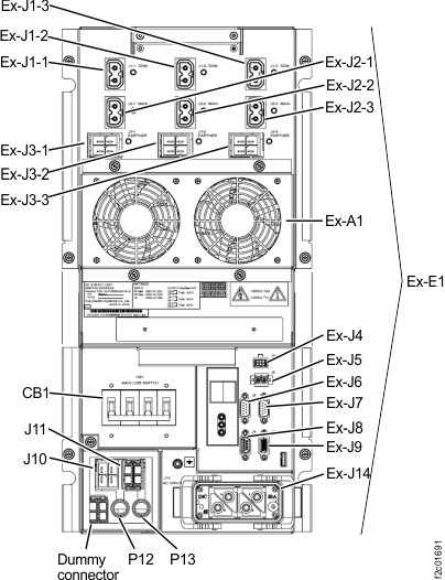
CB1 MAIN LINE SWITCH Off (down) On lower left of each DC-UPS (right rear of rack) Figure 6 RPC card DIP switches 1, 2, 4, 5, 6 (Both cards)
Off (left) Both RPC cards (upper right of rack) Figure 2 RPC card DIP switch 3 (Both cards)
Off (left) Only if LR card (Figure 4) is installed. (upper left rear of rack) Figure 2 and Figure 4 On (right)
Only if ZLR card zSeries power feature is installed (upper left rear of rack) Figure 2 and Figure 5 Local Remote switch Local (left) LR card or ZLR card (upper left rear of rack) C6 in Figure 3, Figure 4, and Figure 5 Figure 1. UEPO switch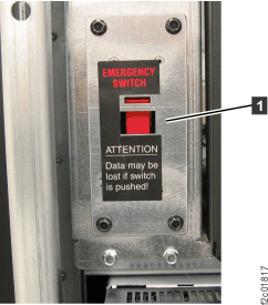 Figure 2. Location codes for the RPC cards (Model 961)
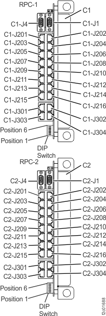 Figure 3. Base rack locations, front and rear
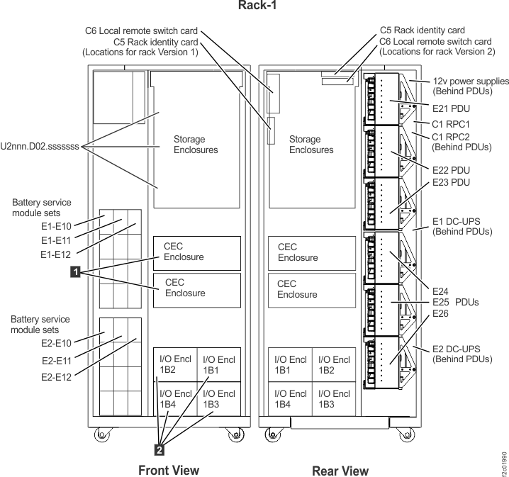 Figure 4. Location codes for the local remote switch card
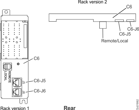 Figure 5. Location codes for the zSeries local remote switch card
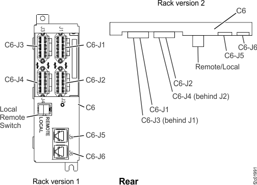 Figure 6. Location codes for the DC-UPS (Models 961, 96E) (rear)