DS8000 Service Documentation Version 6.3.3
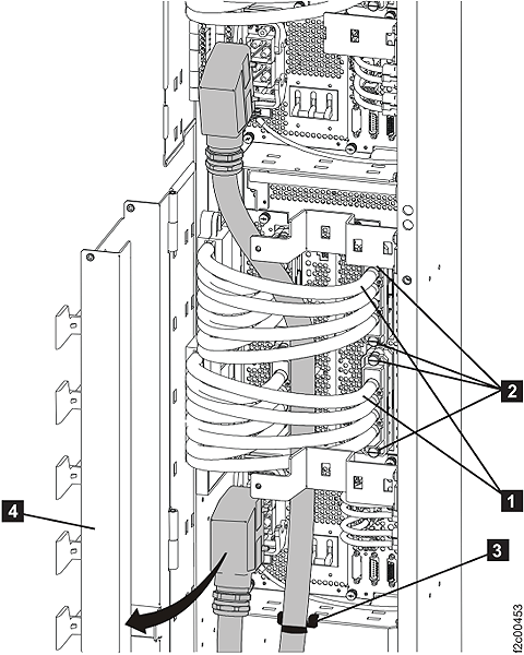
Routing the mainline power cables
Procedure
- Route but DO NOT CONNECT the mainline power cables.
Refer to Figure 1 to
complete the following steps:
- If this is on a raised floor, route the cables down through the floor cutout and near the customer power connectors.
- If this is not on a raised floor, route the cables underneath the frame behind the rear caster so they exit to the side. The cables must not exit the rack in the front or rear service areas.
CAUTION:Do not connect the mainline power cables to customer power until instructed to do so.Figure 1. Routing the mainline power cables