DS8000 Service Documentation Version 6.3.3
Preparing the existing rack
Procedure
- The expansion racks must be fully installed one at a time. Do not use the following sections to install more than one expansion rack at the same time.
- Ensure you use the primary
management console to perform this installation.
- The primary management console should be labeled MC 1 on the front of the HMC keyboard/tray.
- You can verify the management console role (primary
or secondary) by using the Query/Activate HMC Role Selection menu
option.
- From the navigation area, click HMC Management.
- In the right work area, go to the Storage Server HMC Tasks section and click Query/Activate HMC Role Selection. The current HMC role is displayed along with the option to change the setting.
- Ensure the HMC power control mode for this
storage facility is set to Manual Power Mode. If it is not in Manual
Power Mode, note the current customer setting and then change the
setting to Manual Power Mode. At the end of the installation, you
will be directed to restore the original customer setting.
- From the navigation area, click Storage Facility Management.
- From the right work area, select the radio button for the existing storage facility. The bottom Task area displays a list of tasks you can select.
- Click Service Utilities.
- Click Storage Facility Power Control.
- If the power mode is already set to Manual, exit the screen and go to the next step.
- If the power mode is not set to Manual, select Manual Power Mode and then click OK.
Note: Selecting manual power mode prevents the storage facility from unexpectedly powering off during this service action if any of the following occur:- The HMC is set to power off or on using customer-determined time of day schedules.
- The remote power control feature is installed and enabled.
- The customer remotely accesses the HMC to power off the storage facility.
- Once the installation process is started with the HMC GUI, do not interrupt the process by rebooting or shutting down the system or the HMC in any way. Doing so will cause an extended recovery process. Instead, contact your next level of support if you encounter any problems during the installation process that are not repaired by using the guided repair procedures.
- Ensure the rack position
you are physically installing is not already logically installed.
- From the navigation area, click Storage Facility Management > storage facility.
- From the bottom Task area, click Service Utilities > Manage FRUs > Show Rack Enclosures. Note: An enclosure location code is displayed for each logically installed rack.
- Is an enclosure location code displayed for the rack
position you are physically installing?
- Yes, stop and call next level of support. Continuing the installation could cause a customer outage.
- No, continue at next step.
- Prepare the rack
for the add expansion rack process:
- From the navigation area, click Storage Facility Management > storage facility.
- From the bottom Task area, click Storage Facility Install/Remove > Install Expansion Rack. A Single Choice Message Box for the storage facility opens.
- You are prompted with the question Were you sent here from MES or install instructions? Click Yes.
Attention: Racks have both an external and an internal (configuration) model number. The external model number is on the MTMS label above the front door latch and on the "Type Model SN" label ("1S" label) on the inside left sidewall at the front and rear of the rack. The internal model number is on the "Rack Configuration" label on the inside left sidewall at the front and rear of the rack, and can be different from the external model.The external rack model number is entered as part of the Rack MTMS during expansion rack installation. There are situations where the internal rack model is displayed (for example, as part of a rack power and cooling location code). This is normal, and does not indicate an installation error.
Table 1. Expansion rack models and configurations Rack Model Rack Configuration Rack Position 242n.95E 242n.95E Rack-2 242n.95E 242n.95F Rack-3 or Rack-4 - For the new expansion rack
that is being installed, a User Input Message Box is
displayed. Use the following instructions to enter the required information
in the three fields.
- Find the expansion rack MTMS on the front
cover above the door latch. Note: DO NOT USE the Rack-1 MTMS from the large Rack-x label to the left of the red UEPO switch behind the front cover.
The MTMS label format is:
Type 2NNN-MMM
S/N XX-YYYYY, where:- 2NNN
- machine type 2421, 2422, 2423 or 2424
- MMM
- model
- XX
- plant of manufacture
- YYYY
- rack serial number
- Enter the Rack MTMS in the format 2NNN-MMM*XXYYYYY Note: The MTMS format is in uppercase with no dash between the XX and YYYYY. Also, note that the asterisk (*) is required. If you enter the MTMS in lowercase, the installation process will hang for several minutes and then fail.
- Enter the Rack Number (2, 3,
4). Note: The base rack that contains the CEC enclosures is always Rack-1. The expansion racks are installed to the right of Rack-1 and are numbered in order: 2, 3, 4.
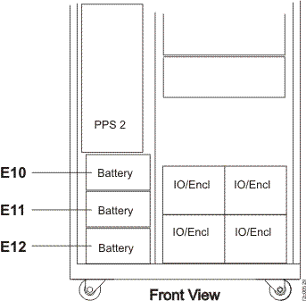
- Enter the number of battery enclosures (E10,
E11, or E12) that contain battery modules.
You will enter a 0 or 1 or 2 or 3. See Figure 1. - Click on Submit. Figure 1. Battery module locations
- Find the expansion rack MTMS on the front
cover above the door latch.
- You have been returned to this step from the HMC expansion rack install process screen. Continue with Verifying the storage facility.