DS8000 Service Documentation Version 6.3.3
Installing and testing the Rack-2 I/O enclosures host adapter cards
Procedure
- In the next Single Choice Message Box, click the SFI that
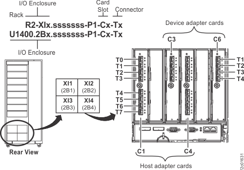
the host adapters will be assigned to, then click Submit. Figure 1. Location codes for device adapter and host adapter cards
- Open
the tailgate and route the host cables.
- In the tailgate, squeeze the black release levers
 , pivot the retention bracket up and
then remove it. Figure 2. Tailgate cable and Fibre Channel cable retention
, pivot the retention bracket up and
then remove it. Figure 2. Tailgate cable and Fibre Channel cable retention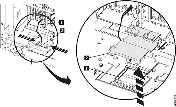
- Feed the host cables
 up through the tailgate and route
them to the destination I/O enclosure and host card adapter ports,
and then plug them in.
up through the tailgate and route
them to the destination I/O enclosure and host card adapter ports,
and then plug them in.
- In the tailgate, squeeze the black release levers
- Open
the top tailgate and route the host cables.
- Unfasten the top tailgate retention bracket, and rotate
it open. See Figure 3. Figure 3. Top tailgate
- Feed the host cables down through the top tailgate. Carefully
route the cables through the channel in the left rear of the rack,
across to the destination I/O enclosure and host card adapter ports,
and then plug them in. See Figure 4. Figure 4. Overhead cable management (top exit) for Fibre Channel, communication, and power cables
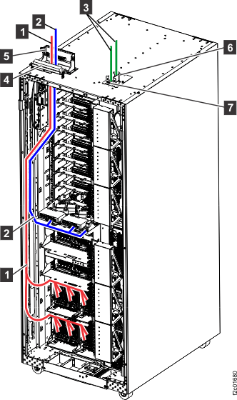
- Unfasten the top tailgate retention bracket, and rotate
it open. See Figure 3.