Before you begin
If you have questions about floor loading and
service clearances of the racks, review the installation site requirements
in the
IBM® System Storage® DS8000® Introduction and Planning
Guide which
is available on the
IBM
DS8000 series Service Documents
CDROM.
Procedure
- Perform the following steps for one expansion
rack at a time. Select the expansion racks in the order they will
be installed (Rack-2, then Rack-3, and so on).
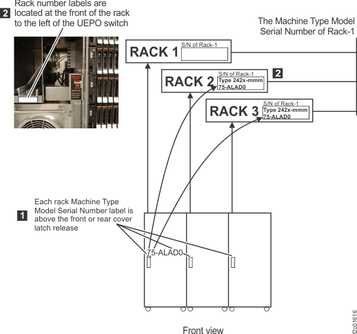
- Each expansion rack has a rack number label 2 ,
located to the left of the UEPO red switch behind the Rack-1 front
cover. See Figure 1.
The label defines the following:
- The position of this rack in a storage facility.
- The serial number of the Rack-1 that the expansion rack must be
re-connected to (these racks have already been configured together
at the factory).
Figure 1. Rack serial number and rack
number labels (Models 951, 95E)
- View the rack number label 2 on
the expansion rack that you are installing. See Figure 1.
- The rack number defines the location of the expansion rack in
the storage facility you are installing.
- The Rack-1 serial number defines the only Rack-1 that this expansion
rack can be installed to.
- The unique serial number of each expansion rack is found
on a small label above the front or rear cover latch release.
Attention: If the Rack-1 serial numbers do not match,
stop the installation and call the next level of support.
- Facing the front of Rack-1, install all additional
racks to the right. Move the expansion rack into position approximately
3" (75mm) from the existing rack.
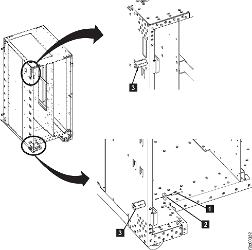
- Locate 4 x spacer studs P/N 22R5046, 7 x spacer mounting
bolts P/N 1621545 and 7 x M8 washers P/N 84X5850 located in the ship
group.
- Install the bottom spacer stud at the rear of the existing
rack (Rack 1 or the expansion rack that is already installed).
- Refer to Figure 2. Install a spacer stud 3 in
the lower rear left corner of the rack using a mounting bolt 1 and
a washer 2 . Leave the bolt loose so that
it will be easier to align the spacer stud with the bolt from the
new frame.
Figure 2. Interrack spacer studs
- In the upper rear left corner of the existing
rack, next to the hinge, there are two holes; one above the other.
Use the lower hole and install a spacer stud 3 using
a mounting bolt 1 and a washer 2 ,
see Figure 2. Do
not tighten the bolt fully as some alignment will be needed. You
can hold the side cover next to the spacer studs to ensure the spring
clips align properly before going to step 9.
Note: On
early frames, it may be necessary to remove the rear left top hinge
and spacer plate to allow the mounting bolt to be inserted. Reinstall
the hinge and plate when the bolt has been tightened.
- On the rear of the expansion rack being installed, perform
the following steps to remove the right cover.
- Open the rear left machine cover.
Note: On some models, the rack
machine type, model, serial (MTMS) label is on the left rear cover, just above the door latch. If
the left rear cover is removed from the rack, ensure that it is reinstalled on the correct rack. If
the cover is not reinstalled on the correct rack, the incorrect MTMS is displayed on the exterior of
the rack, which could result in maintenance errors or other issues. If a reference is needed, the
correct rack MTMS is also shown on the "1S" label, affixed to the upper left inside wall of both the
front and rear of the rack.
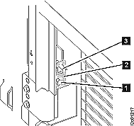
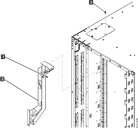
- Remove and retain the two screws 1 and
open the rear right machine cover. Refer to Figure 4.
Note: The
screws must be reinstalled later to prevent non-service personnel
from accessing a hazardous section of the machine.
- On the upper and lower door hinges, loosen the screw 1 and
move the retention plate 2 that prevents
the hinge pin 3 from being removed. Refer
to Figure 3.
Figure 3. Removing rear right cover
- Remove the hinge pins, remove the rear cover and place
it in a safe location.
Figure 4. Removing retaining screws on right rear machine cover
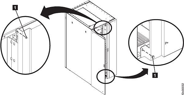
- Return to the front of the racks. Do not remove any front
covers. Install 2 spacer studs on the front left of the storage expansion
being installed.
- Install a spacer stud in the lower front left
corner of the rack using a mounting bolt and a washer. Do not tighten
the bolt fully as some alignment will be needed.
- Install a spacer stud in the upper front left
corner of the rack using a mounting bolt and a washer. If there
are two frame holes near the hinge, use the same hole (upper or lower)
as you did at the rear of the rack. Do not tighten the bolt fully
as some alignment will be needed.
- Move the expansion rack being installed into its final
position.
- At the rear, secure the expansion rack being installed
to the existing rack using one bolt and washer in the upper position
only. The bolt is screwed into the spacer stud previously installed.
Do not tighten the bolt fully.
- At the front, insert two bolts and washers from the left
rack and screw into the spacer studs previously installed in the right
rack. When the alignment is correct, tighten all the bolts that have
been installed.
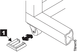
- Install the wheel chocks 1 (located
in the ship group) on all four casters. If caster locks are available,
engage the caster locks on all casters. Refer to Figure 5.
Figure 5. Wheel (wedge) chocks
- If you are installing Rack-2 does it have an
upper "funnel" bracket 2 inside
at the rear top left of the rack? See Figure 6.
- Yes, go to the next step.
- No, go to step 18.
Figure 6. Removing top tailgate cover
plate
- Looking down at the top left rear of the rack,
inspect the top tailgate cover plate screw 3 .
See Figure 6.
- If the screw is installed from the top (only screw head is
visible), go to the next step.
- If the screw is installed from inside the rack, (only threaded
end is visible) to go step 17.
- The screw is installed from the top of the rack.
Install the screw from inside the rack and then install the top tailgate.
- Remove and discard the nut 1 securing
the upper "funnel" bracket 2 of
the host cable channel. See Figure 6.
- Remove the long screw 3 from
the top of the rack.
- Install the long screw 3 from
inside the rack. The threaded end of the screw will extend out the
top of the rack.
- At the top of the rack, remove the three screws that
secure the cover plate to the top of the rack. Remove the cover plate.
- Store the cover plate in the document enclosure at the
front top left of the rack.
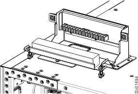
- Position the tailgate assembly over the opening at the
top of the rack. See Figure 7. Secure
the assembly with the three screws that were removed in step d.
- Go to step 18.
- The
screw is installed from inside the rack. Install the top tailgate.
- Looking down at the top of the rack, remove the three
screws around the opening for the funnel bracket. See Figure 6. The rack
was shipped with the cover plate already removed and stored in the
document enclosure at the front top left of the rack.
- Position the tailgate assembly over the opening at the
top of the rack. See Figure 7. Secure
with the three screws that were just removed.
- Go to the next step.
- Do you have additional expansion racks to install?
- Yes, return to step 1 of this section
to install the next expansion rack.
- No,
go to the next section.