DS8000 Service Documentation Version 6.3.3
Connecting a new storage facility to an existing storage complex
Before you begin
DANGER
An
electrical outlet that is not correctly wired could place hazardous
voltage on the metal parts of the system or the devices that attach
to the system. It is the responsibility of the customer to ensure
that the outlet is correctly wired and grounded to prevent an electrical
shock. (D004)
About this task
Attention: If you will be installing more than one new storage
facility to an existing storage facility complex, completely install
one storage facility at a time.
Procedure
- At the rear of the new Rack-1 you are installing,
connect the black Ethernet cable as follows:
- For 16-port Ethernet switches, connect the black Ethernet
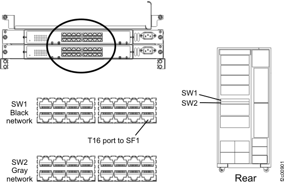
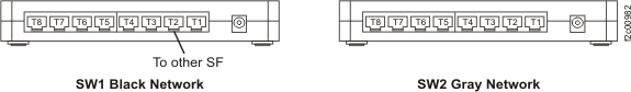
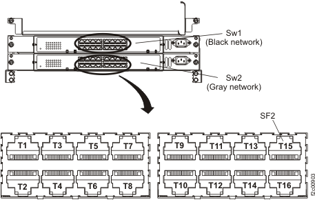
cable to the upper Ethernet switch (SW1) port T16. Figure 1. Ethernet cable (Black) to upper 16-port Ethernet switch (SW1)
- For 8-port Ethernet
switches, connect the black Ethernet cable to left Ethernet switch
(SW1) port T2. See Figure 2. Figure 2. Ethernet cable (Black) to left 8-port Ethernet switch (SW1)
- For 16-port Ethernet switches, connect the black Ethernet
cable to the upper Ethernet switch (SW1) port T16.
- At the rear of the new Rack-1 you are installing,
connect the gray Ethernet cable as follows:
- For 16-port Ethernet switches, connect the gray Ethernet
cable to the lower Ethernet switch (SW2) port T16. See Figure 3 Figure 3. Ethernet cable (Gray) to lower 16-port Ethernet switch (SW2)
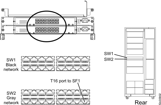
- For 8-port Ethernet
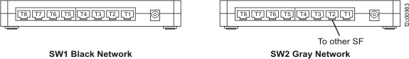
switches, connect the gray Ethernet cable to the right Ethernet switch
(SW2) port T2. See Figure 4. Figure 4. Ethernet cable (Gray) to right 8-port Ethernet switch (SW2)
- For 16-port Ethernet switches, connect the gray Ethernet
cable to the lower Ethernet switch (SW2) port T16. See Figure 3
- At rear of the existing
Rack -1 in SF1, do the following:
- For 16-port Ethernet switches, connect the black Ethernet
cable to the upper Ethernet switch (SW1) port T15. See Figure 5 Figure 5. Black Ethernet cable connection to upper 16-port Ethernet switch (SW1)
- For 8-port Ethernet
switches, connect the black Ethernet cable to left Ethernet switch
(SW1) port T2. See Figure 6. Figure 6. Ethernet cable (Black) to left 8-port Ethernet switch (SW1)
- For 16-port Ethernet switches, connect the black Ethernet
cable to the upper Ethernet switch (SW1) port T15. See Figure 5